 |
|
Contact Alex Chernov,
Certified Heater Mason
Member of MHA
WETT#8347
Tel. (519) 938-9166
Cell (416) 708-8139
alex.chernov@stovemaster.com
|
|
 |
Filed Testing of Double-Bell heaters.
By Alex Chernov
www.stovemaster.com
Introduction
I consider this testing as a beginning of a research that I would like to continue doing in the future. It is very true that "the first thing you realize while doing testing is that you need more testing". I believe these are Norbert’s words. Norbert Senf arguably has performed most testing of masonry heaters ever done in North America. I would like to express my high appreciation of his help in selecting the right equipment as well as his valuable input on various technical issues.
As a custom heater builder, I would like to be able to use the best technology to build the best heaters possible. This is the main reason why I am interested in testing. There is really no other way to judge about performance of masonry heaters with confidence. I am using the System of Free Gas Movement I have learned from Igor Kuznetsov, a great Russian stove designer and mason, to design all heaters and stoves I build. Although all my heaters and all four to five thousand heaters (!) built by Igor and his team of stove masons over years perform very well and enjoy good reputation, no testing of bell heaters was ever done. The first approach to such testing was the project and the test that we have done at the Wild Acres'06. Due to numerous reasons such as lack of time to build the proper variations, outside setting, weather differences and other, that testing didn't give us any clear idea. In fact, it raised even more questions. The testing that we have done together with Norbert Senf and Jerry Fricsh on two bell heaters at my home right after the MHA meeting, has shown very high efficiency of both heaters, but high CO levels as well. CO measurement, as we have found later, wasn't performed properly, however there were enough evidence that indicated the combustion was on a dirtier side.
These tests have prompted me to get TESTO gas analyzer to do more testing of bell heaters in order to:
- - tune up the firebox system for cleaner combustion;
- - find out if high efficiency indeed is a common feature of bell heaters, as it was claimed by Igor Kuznetsov;
- - prove (and mainly for myself) that the Bell System is at least as good as other systems of design.
My general visual observations of bell heaters build by Igor's team or by myself featuring old design of the fireboxes led me to a conclusion that the combustion may not be up to the ideal. The first test has proven this idea. Immediately, I have begun working on improving the firebox design. Originally, the fireboxes in all bell heaters featured quite large grate (under fire air supply) and had no provision for secondary air supply. Norbert told me at that time that his past testing clearly indicated that under fire air supply was the major reason for the dirty burn. Having realized this, Norbert eliminated grate from his firebox design that improved combustion significantly. I wanted to find the balance, as I had feelings there should be a grate, but probably much smaller then I had used before.
Based on our long conversations with Igor Kuznetsov and several variations of firebox designs built in new heaters, I have developed a new firebox system that featured smaller grate, secondary air supply through either the door (if it had provisions) or through the slot in front of the door, and preheated secondary air supply through the side walls of the firebox. The first heater built with this firebox system performed remarkably well as was assessed visually. I just had to do some testing to prove it.
This winter, I have got a permission to perform some testing from several clients that had heaters with the new firebox system. One heater was build the next door, and I had the opportunity to do several runs with some variations of air supply system to find out what works the best for combustion. The test results with description of heaters are below. My conclusions will follow at the end.
Although I clearly understand that to be scientifically correct, each version has to be tested at least 10 or 20 times to find if the results are reliable. However, I don't have this opportunity. I don't have a specialized lab, I don’t have time for this time consuming procedure as I keep working and have a very busy schedule. This winter, I have spent over a week of my between-the-projects-free-time away from my family every evening doing testing to gather this information. Regardless of the fact that these are just few test runs, I find the results interesting and helpful for myself. I also believe they may be interesting for other stove masons.
Notes:
- I haven't done testing on heaters in my home with the original, non-modified fireboxes. We have done this testing with Norbert Senf and Jerry Frisch and found, as was stated before, that the combustion was on a dirtier side. Test report is here: http://www.mha-net.org/docs/v8n2/wildac06c.htm I could try to run another test of the original fireboxes, however, it probably wouldn't have reliable results as my TESTO has a low limit for CO measurement (4000ppm), and I wouldn't be able to gather exact data. I have decided to modify the fireboxes and run the test of new versions instead.
- In a typical lab test setting, the analyzer's probe should be inserted into the chimney flue approximately immediately above the chimney damper. In contra flow and other bottom-vented designs it means that temperature is measured in the chimneystack outside the heater's core. Due to the fact that all my test heaters were "real-life" heaters owned by my clients, and due to the technical impossibility to access the described point in many cases, all tested heaters except Whole Village heater were tested by inserting the probe through the shut-off damper slot that is located within the upper chamber of the heater (shut-off damper is typically located at the lower part of an updraft channel leading to the chimney as most of my heaters are top vented. This channel is often located in the middle of the upper "bell"). Therefore, it would be logical to expect that measured flue temperatures should be somewhat lower if they would be measured properly. Such difference in temperatures could result in even higher efficiency numbers. However, this is a presumption only.
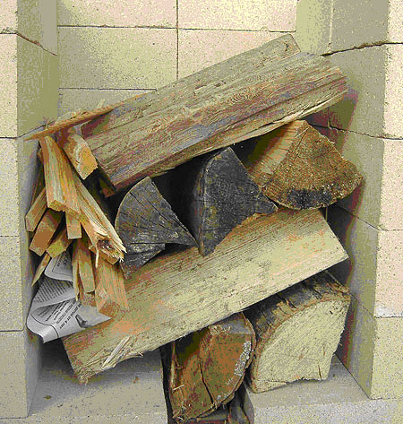
- Fuel loading and starting technique used in all test runs is "side-top kindling" developed by Norbert Senf. (see picture). Observations and test results proved substantial benefits of such technique. Logs get ignited from a top corner, and flames travel gradually in a diagonal pattern to eventually ignite all the pile, resulting in low start-up emissions in comparison with the "old way" (kindling and paper is placed underneath the logs).
- Tests were performed using TESTO-325M measuring Stack Temperature, Oxygen, and CO levels. CO2 levels were calculated from O2 levels using TESTO formulas.
- Test results were entered into a CONDAR test spreadsheet provided by Norbert Senf. All final results were recorded from the spreadsheet. It should be noted that formulas in spreadsheet use particulate emissions data to calculate efficiency numbers. Due to impossibility to measure PM-emissions in my field tests, average numbers for PM levels entered into the spreadsheet by Norbert Senf were used in the calculations. We believe that this provides pretty reliable results that would have minimal deviation from result were actual PM numbers are used.
- Despite of the fact that some loads burned longer than 2 hours (to the point when no embers left), all test results used 2-hour run length for a fair comparison between each other and between the results achieved in Lopez labs testing available on-line.
- In comparison to Europe, where CO emissions are regulated, it is PM emissions that are regulated in the North America. Unfortunately, there is no easy way to measure PM. It requires special expensive equipment and lab setting. Therefore, CO levels measurements were the only tool I had to judge about emissions. Although such approach may be considered incomplete, in my situation it is the only way that gives me relative comparison of different modifications in firebox design.
Description of the test heaters:
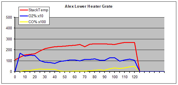
- AL: Lower of two stacked heaters in my home. This is a large multifunctional heater that has a cook-top over a large firebox, a bake oven, and a 5ft-long heated bench with heated back. The firebox doesn't have any provisions for the secondary air supply through the walls. The heater's UPO door has built-in air wash-secondary air system. The firebox originally had a very large grate. For this test, I have covered part of the grate with firebricks to get grate dimensions similar to other tested heaters (5x15'').
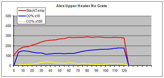
- AU: Upper of two stacked heaters in my home. It is a medium size heater with a "white" bake oven and a heated bench at the side opposite to firebox. The firebox has 5x15'' grate. No provisions for the secondary air. Norbert's door without air supply. Originally, I had a very narrow (3/8'' to 3/2''wide) slot behind the door for air wash. This size didn't work well. For this test, I have covered up the grate 95% with firebricks, and increased size of the air wash slot to 1 1/4''x 12'' to become the main combustion air supply slot. Norbert''s report about construction of my heaters is available here:
http://www.mha-net.org/docs/v8n2/docs/Workshop0509.htm
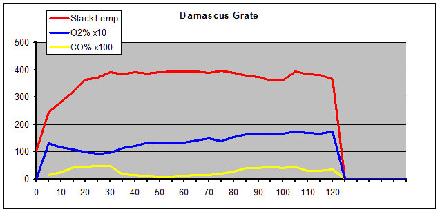
- DS: Damascus Heater. A symmetrical 48''x32''double-bell heater with a direct bake-oven above the firebox. The heater is 9ft tall. The firebox has a 5x15'' grate, UPO door with built-in air wash system, and secondary air supply through 3/2''-wide channels in-between the firebox walls and a single row of air outlets at the top of the firebox.
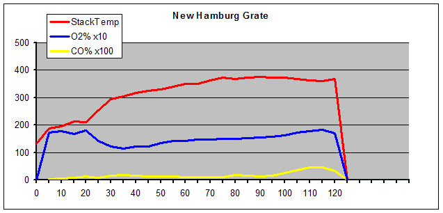
- NH: New Hamburg Heater. An L-shaped heater with larger firebox and direct bake oven above the firebox. The firebox gas 5x15 grate, UPO door with built-in air wash system, and secondary air supply through 3/4''-wide channels in-between the firebox walls and 3 rows of air outlets located around perimeter of the firebox. There are also several small secondary air outlets located directly in the dry joint.
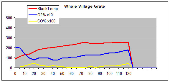
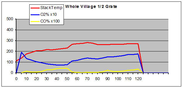
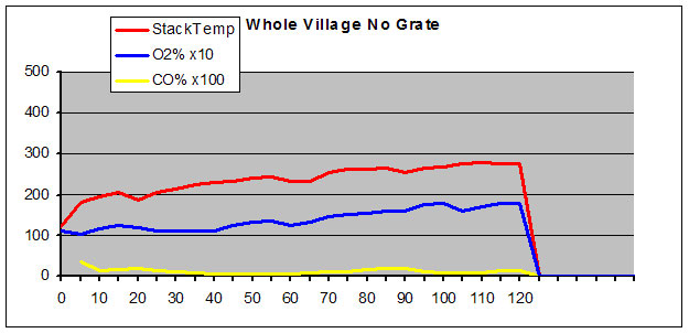
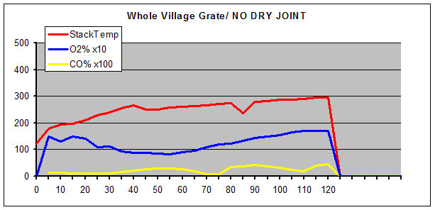
- WV: Whole Village Heater. A large non-symmetrical heater with a direct bake oven above the firebox and a 5ft-long heated bench with heated back. The original firebox design features: 5x15'' grate, an 1 3/2'' x 9'' slot in front of the Norbert's door, and secondary air supply through 3/4''-wide channels in-between the firebox walls and 3 rows of air outlets located around perimeter of the firebox. There is also a small secondary air outlet located directly in the dry joint. There were several test runs with original and modified air supply systems. Description of the versions: WV-01: original firebox design; WV-02: grate is completely covered; WV-03: half of the grate is covered; WV-04: grate is open and a dry joint is plugged.
Pictures and description of the tested heaters are available here: http://www.stovemaster.com/html_en/gallery.html
Conclusions and comments
Efficiency results.
Overall, all tested bell heaters with all modifications have shown very high efficiency numbers, where heat transfer efficiency value of 84.9% (AL-01 & WV-01) was the highest, and 76.8% (DS-01) was the lowest. Both low oxygen levels (the lowest average 8.71%) and low stack temperatures (the lowest average 212F) contributed to high efficiency numbers.
The tested bell heaters had different shape and size. All the heaters had firebox of approximately the same size and volume. Test results have proven my idea that larger heaters would have higher efficiency than smaller heaters with the same firebox. It also proves, that in the most common shape of heaters (36x48'' rectangular) 18x18'' firebox is too large to achieve highest possible efficiency in the available volume (DS-01, heater in such shape and size, had the lowest efficiency number of all tested). Both heaters with extra heat exchange volume (heated benches), AL-01 and WV, had the highest efficiency numbers.
These results allow me to conclude that bell heaters do offer higher efficiency despite of their size, shape and functions.
CO emissions results
All tested heaters, despite of modifications to air supply system, had average CO levels in the range between 0.13% and 0.28% that is within the 0.30% limit set up in the EU draft regulations document (we don't have any guidance for CO levels in North America.).
Heaters featuring under fire air supply (grate) and no preheated secondary air supply thorough the sides of the firebox generally shown higher CO emissions. Heaters with 3 rows of air outlets for the secondary air supply in the firebox walls were burning cleaner even with full under fire grate. Version WV-02 with over fire air supply and secondary air supply (no grate) was the cleanest, featuring average CO levels of 0.13%. However, the cycle was much longer due to the fact that combustion was very slow at the coals stage. Half grate version, on my opinion, gave the best results.
My conclusion is that a small under fire grate and secondary air supply system with wider slots and 3 rows of air outlets are beneficial to facilitate clean combustion. Presence of a small under fire grate doesn't seem to have a great negative influence on emissions. The grate could also be partially covered with one of the logs while loading to create an "automatic grate damper".
In regards to the under fire versus over fire question, it is interesting to note that none of all heaters, kahelofens, cookers etc I have seen at the Austrian Kahelofen Fair this January had under fire air supply. All had over fire air supply at the door with secondary air supply through the walls. The only company that had grates in their heaters, Finnish "Nunnaunni", had a special grate that allowed to open and close air supply thorough the grate. This seems logical considering that Austria and Germany have the toughest CO emissions level limit of 0.17%.
| Heater ID |
|
WV-01 | WV-02 | WV-03 | WV-04 | AL-01 | AU-01 | NH-01 | DS-01 |
| Overall Efficiency % |
81.4 | 79.94 | 80.33 | 79.47 | 81.93 | 77.86 | 74.46 | 73.09 |
| Heat Transfer Efficiency % |
83.9 | 82.06 | 82.78 | 82.4 | 83.99 | 80.95 | 77.23 | 76.81 |
| Combustion Efficiency % |
97.01 | 97.42 | 97.03 | 96.44 | 97.55 | 96.18 | 96.42 | 95.17 |
| g/kg CO |
22.05 | 17.65 | 21.64 | 26.95 | 17.73 | 28.7 | 25.38 | 37.13 |
| g/kg CO Condar |
1.27 | 1.52 | 1.34 | 1.32 | 1.15 | 1.47 | 1.84 | 1.63 |
| Average Stack Temp. deg F |
212 | 236 | 237 | 250 | 223 | 255 | 314 | 359 |
| Average O2 % |
9.96 | 11.55 | 10.29 | 10.09 | 8.71 | 11.87 | 12.75 | 11.43 |
| Average CO % |
0.19 | 0.13 | 0.19 | 0.24 | 0.17 | 0.21 | 0.17 | 0.28 |
| Average CO/CO2 ratio |
0.034 | 0.023 | 0.028 | 0.036 | 0.019 | 0.035 | 0.039 | 0.051 |
| Fuel Surface/Volume Ratio |
3.06 | 2.78 | 3.12 | 3.08 | 2.71 | 3.04 | 2.81 | 3.15 |
| Number of pieces |
9 | 7 | 8 | 8 | 7 | 8 | 7 | 9 |
| Moisture % |
18.4 | 18.1 | 17 | 18.6 | 18 | 17.4 | 20 | 17 |
| Total Fuel Weight Lbs. |
49.5 | 49.1 | 47.8 | 47.6 | 50 | 51.7 | 49.4 | 48.4 |
| Average Surface Temp. before test (deg F) |
| 100 | 100 | 100 | 95 | | 100 | 95 |
| Average Firebox Walls Temp. before test (deg F) |
| 136 | 133 | 130 | 115 | | 133 | 110 |
| Bake Oven Temp. before test (deg F) |
| 176 | 156 | 171 | 120 | | 174 | 150 |
| Bake Oven Temp. @ the end of the test (deg F) |
| 535 | 590 | 618 | 490* | | 535 | 550 |
| Time since last firing (hours) |
| 23 | 23 | 23 | 31 | | 23 | 24 |
* Temperatures for this heater were measured one extra time 15hrs after the test fire: Surface 155F; Bake Oven 240F; Firebox 220F.
| Description of heater ID: |
| WV-01 | Whole Village Heater Grate, Advanced Secondary Air Supply |
| WV-02 | Whole Village Heater, NO Grate, Advanced Secondary Air Supply |
| WV-03 | Whole Village Heater, 1/2 Grate, Advanced Secondary Air Supply |
| WV-04 | Whole Village Heater, Grate, NO DRY JOINT, Adv. Secondary Air Supply |
| AL-01 | Alex's Lower Heater, Grate, No secondary Air Supply |
| AU-01 | Alex's Upper Heater, NO Grate. No Secondary Air Supply |
| NH-01 | New Hamburg Heater, Grate, Advanced Secondary Air Supply |
| DS-01 | Damascus Heater, Grate, Simplified Secondary Air Supply |

|
 |
|
|
|
 |
|